
TUCer / Diploma thesis · Technical University of Crete
CFRP Composite Wheel.
A single-piece, tubeless carbon-fibre wheel replacing a two-piece glued rim — from RVE-based composite modelling through a three-mold manufacturing evolution to instrumented physical validation.
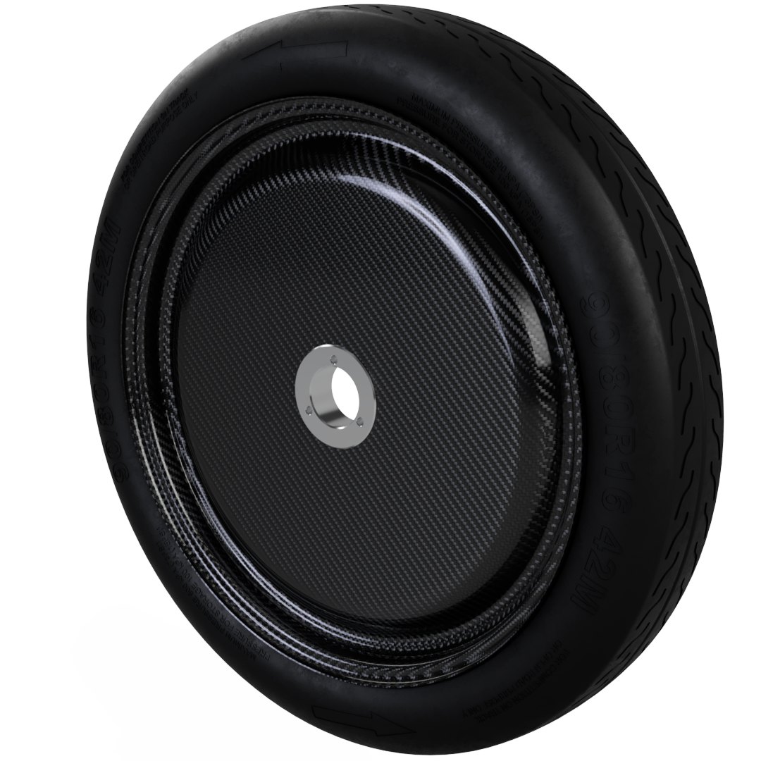
FIG. 01 — CFRP composite wheel, TUC diploma thesis
Design
The old wheel was a two-piece rim glued together, requiring an inner tube and concentrating load in the adhesive joint. The new design is single-piece and tubeless: Michelin's 3.00 B rim geometry (chosen over the alternative for a lower rolling-resistance coefficient at the competition's 35 km/h average speed) retains the tire at operating pressure with no tube at all.
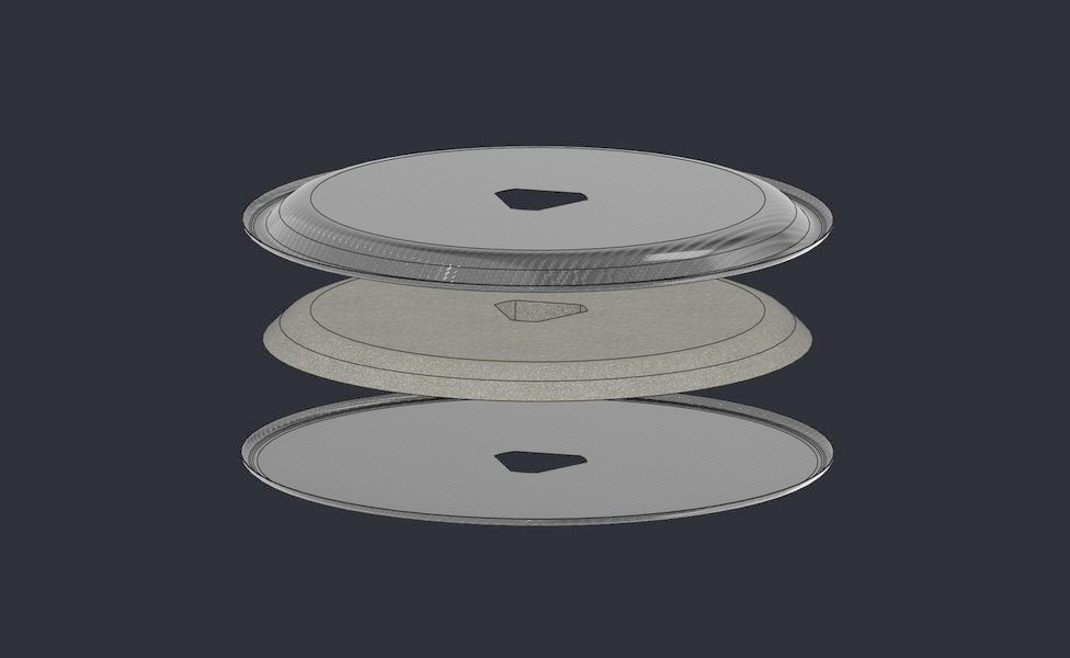
The sidewall replaces spokes with a foam-core CFRP sandwich — evening load distribution, cutting aerodynamic drag, and resisting bending and buckling. The hub is deliberately simple: a two-piece triangular center bolts to a permanent adapter left on the vehicle, which carries the brake disc and bearings. Removing the wheel no longer disturbs the brake caliper.
Materials & FEA
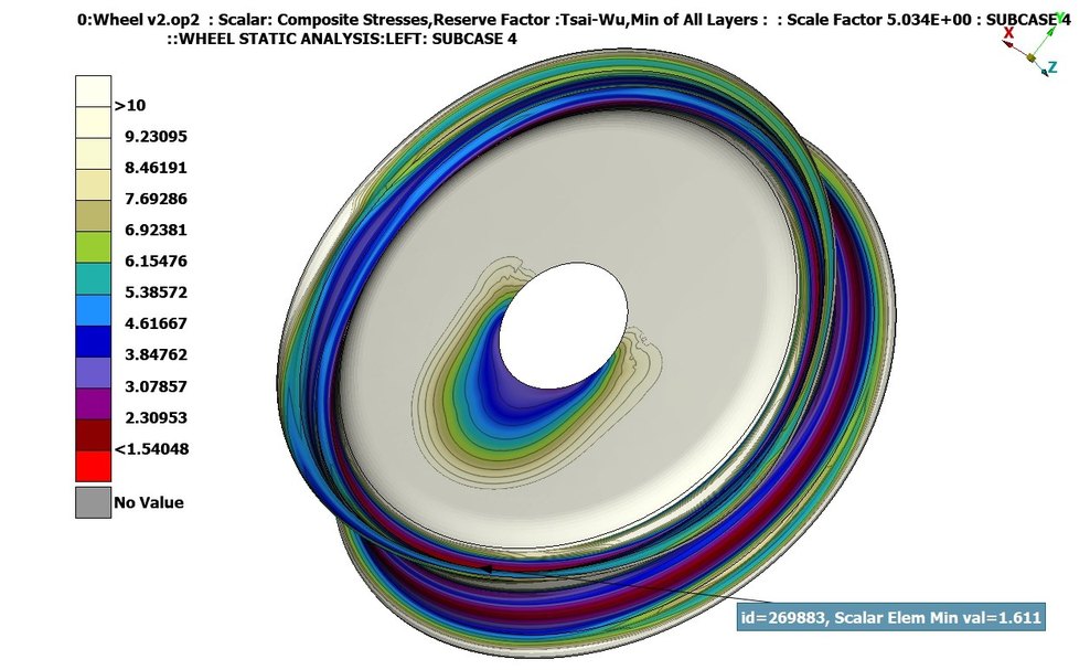
The laminate — twill 2×2 T300 carbon fibre in Resoltech 1050/1058s infusion epoxy — was characterized by RVE (Representative Volume Element) homogenization in ANSA/EPILYSIS: six strain-controlled load cases on a periodic microstructure model, yielding orthotropic properties (E1 ≈ E2 ≈ 52.4 GPa for the balanced weave, fibre volume fraction 0.454) fed into ply-level FEA with per-ply Tsai–Wu tracking.
Five load cases were simulated per candidate — four static (weight, cornering, braking, internal pressure) plus a transient pothole impact — and 9 candidate layups were scored on margin, mass and stiffness (full breakdown below). The winner, a 20 mm-core layup at 635 g, held a minimum Tsai–Wu reserve factor of 1.54 across all five subcases; thinner or coreless variants either failed outright or scored far lower.
Nine-candidate layup study
Any candidate with a reserve factor below 1 in any subcase is rejected outright and scores 0%; the rest are ranked by S = 3·max(RF) / (m³·max(u)1.5), with mass m in grams and displacement u in millimetres. The exponents show the function was designed rather than fitted: a 10% mass increase costs about 27% of the score, and that same 27% needs roughly 14% more displacement.
| Code | Description | Mass (g) | Min RF | Max disp. (mm) | Score |
|---|---|---|---|---|---|
| R6W6 | 20mm core wall | 635 | 1.540 | 6.75 | 100% |
| R6W6 | 20mm core wall + 2mm core rim | 776 | 2.479 | 5.96 | 93% |
| R5W6 | 20mm core wall | 590 | 1.203 | 7.47 | 85% |
| R6W8 | 20mm core wall | 659 | 1.211 | 6.45 | 76% |
| R6W6* | 20mm core wall + LR | 660 | 1.592 | 7.70 | 75% |
| R6W6 | 15mm core wall | 596 | 1.521 | 10.67 | 61% |
| R6W6 | 10mm core wall | 557 | 1.485 | 16.45 | 39% |
| R6W6 | No core | 478 | 0.147 | 363.60 | 0% |
| R4W6 | 20mm core wall | 545 | 0.894 | 20.84 | 0% |
Sorted by score, the function's own ranking. The bottom two failed outright — reserve factor below 1 in at least one subcase — and score zero by definition; they are published, not omitted. Five load cases per candidate: four static (weight, cornering, braking, internal pressure) plus a transient pothole impact, run as subcases 1–5. Subcase 5 is confirmed as the impact case; the source does not establish which static case is subcase 1, 2, 3 or 4 — TODO: Mike — confirm which subcase is which load case. FIG. 03 above plots subcase 4 (min element 1.611); the table's governing minimum, RF 1.540, falls in subcase 3. R6W6*'s LR suffix is undefined in the thesis text — TODO: Mike — what does LR expand to in the R6W6* row?
View full per-subcase data
| Code | Description | Mass (g) | Rejected | Reserve factor (Tsai–Wu) by subcase | Max displacement (mm) by subcase | Score | ||||||||
|---|---|---|---|---|---|---|---|---|---|---|---|---|---|---|
| S1 | S2 | S3 | S4 | S5 | S1 | S2 | S3 | S4 | S5 | |||||
| R6W6 | 20mm core wall | 635 | No | 2.033 | 1.863 | 1.540 | 1.611 | 2.036 | 2.166 | 2.289 | 6.748 | 5.667 | 2.152 | 100% |
| R6W6 | 20mm core wall + 2mm core rim | 776 | No | 2.869 | 2.841 | 2.479 | 2.752 | 2.875 | 1.446 | 1.568 | 5.963 | 4.253 | 1.440 | 93% |
| R5W6 | 20mm core wall | 590 | No | 1.613 | 1.466 | 1.203 | 1.313 | 1.614 | 2.685 | 2.863 | 7.467 | 6.272 | 2.686 | 85% |
| R6W8 | 20mm core wall | 659 | No | 1.618 | 1.470 | 1.211 | 1.502 | 1.620 | 2.489 | 2.663 | 6.446 | 5.074 | 2.485 | 76% |
| R6W6* | 20mm core wall + LR | 660 | No | 2.084 | 1.911 | 1.592 | 1.632 | 2.087 | 1.883 | 1.968 | 7.704 | 6.780 | 1.868 | 75% |
| R6W6 | 15mm core wall | 596 | No | 2.026 | 1.857 | 1.521 | 1.594 | 2.027 | 2.445 | 2.576 | 10.670 | 8.862 | 2.471 | 61% |
| R6W6 | 10mm core wall | 557 | No | 2.014 | 1.848 | 1.485 | 1.548 | 2.019 | 3.048 | 3.200 | 16.450 | 13.130 | 3.053 | 39% |
| R6W6 | No core | 478 | Yes | 1.566 | 1.379 | 0.147 | 0.180 | 0.899 | 39.330 | 43.850 | 363.60 | 280.10 | 77.50 | 0% |
| R4W6 | 20mm core wall | 545 | Yes | 1.222 | 1.101 | 0.894 | 1.063 | 1.223 | 10.434 | 12.039 | 20.837 | 12.792 | 3.586 | 0% |
Source: analysis.tex, TUCer diploma thesis, table tab:results_table and its scoring-function block, verbatim.
Manufacturing
Tooling went through three iterations. The first mold, machined from MDF, proved the process was feasible in the lab but suffered from moisture sensitivity, heat deformation, and resin waste. The second, machined from UHMWPE on a CNC router, released cleanly without release agents but couldn't be fully sealed for the rim's more complex geometry. The third and final rim mold — a two-piece gelcoat–fiberglass–vinylester composite cast from a CNC-machined foam positive — produced three rims with no deformation or wear.
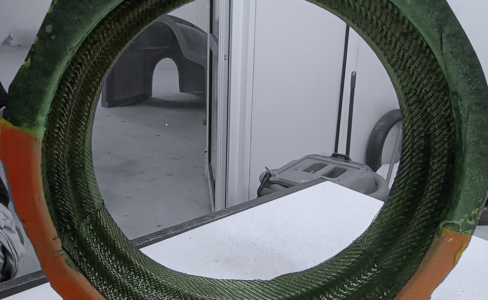
Parts were built by vacuum infusion (VARTM): 18 fabric pieces for the rim and 6 plus a core for the sidewall, laid up with the mold's smooth face at the tire interface and its peel-ply rough face used as the bonding surface, needing no sanding. Each part cured for 16 hours at 60°C in a purpose-built oven — see the curing oven case study — then the two halves were bonded with epoxy and post-cured.
Results & validation
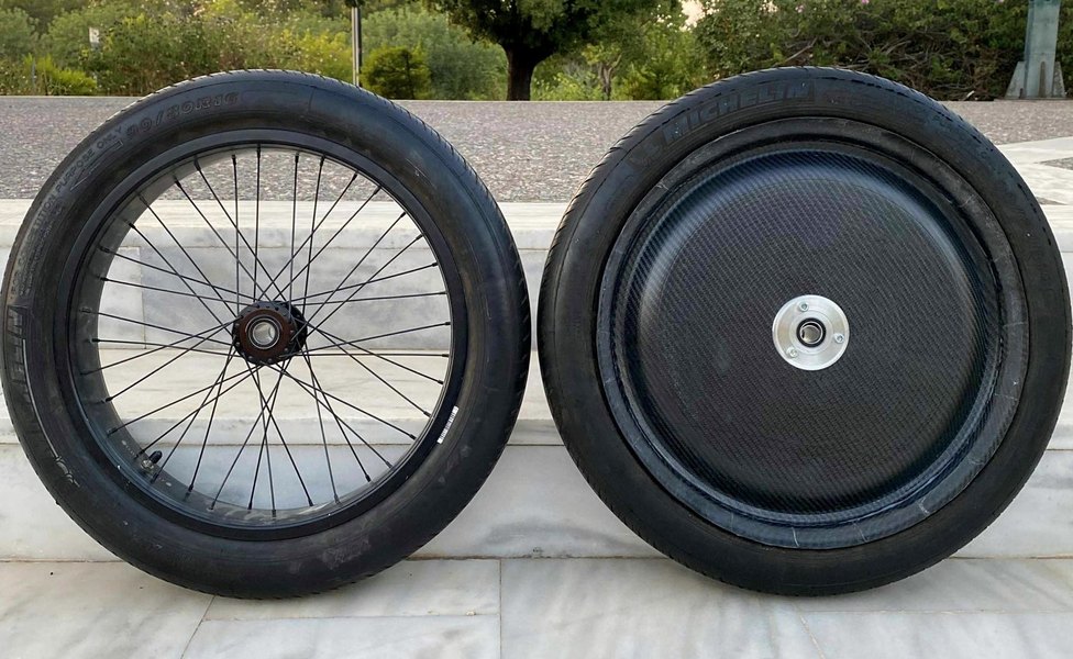
The finished wheel assembly weighs 2841 g against the old wheel's 3515 g — a 19.2% reduction (674 g), with the wheel structure alone down 37.9% and the hub down 48.6%. At vehicle level, that's roughly 2.7 kg saved across four wheels.
Physical validation ran on a custom-built instrumented test bench: a pressure test held +20% over operating pressure with no cracks, a fatigue test ran 40 kg at max speed for a duration equal to three race lengths with no damage, and comparative energy testing measured 44–59% lower specific energy (Wh/km) for the new wheel under load, with rotational inertia consistently 11–47% lower across all four test scenarios.